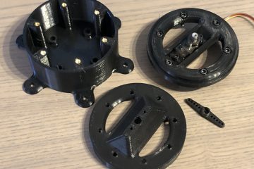
Modellbezeichnung: MT-2011
Download: https://www.printables.com/de/model/666090
![](http://blog.zeppelinium.de/3d/wp-content/uploads/sites/4/2023/01/IMG_5393-1024x768.jpeg)
![](http://blog.zeppelinium.de/3d/wp-content/uploads/sites/4/2023/01/IMG_5394-1024x768.jpeg)
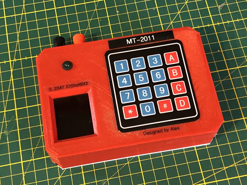
Am ESC Stecker (3 Pin) sind nur 2 Pins belegt: Masse und Signal. Pin-Belegung wurde entsprechend auf dem Aufkleber gekennzeichnet.
Das Gerät darf nur an 5V angeschlossen werden.
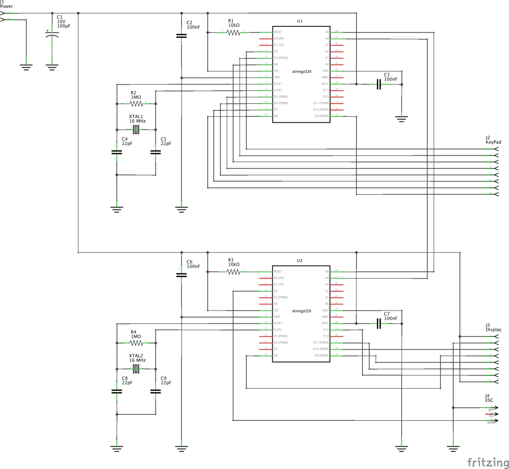
![](http://blog.zeppelinium.de/3d/wp-content/uploads/sites/4/2023/01/IMG_5398-1024x768.jpeg)
![](http://blog.zeppelinium.de/3d/wp-content/uploads/sites/4/2023/01/IMG_5425-1024x768.jpg)
![](http://blog.zeppelinium.de/3d/wp-content/uploads/sites/4/2023/01/MT-2011-Panel-1024x768.jpg)
![](http://blog.zeppelinium.de/3d/wp-content/uploads/sites/4/2023/01/IMG_1147.png)
![](http://blog.zeppelinium.de/3d/wp-content/uploads/sites/4/2023/01/IMG_1146.png)
![](http://blog.zeppelinium.de/3d/wp-content/uploads/sites/4/2023/01/IMG_1145.png)
Elektronik
MT-2011 besteht aus zwei µC je mit folgenden Aufgaben:
- U1: Keypad Controller. Es erkennt Eingabe am Keypad und bereitet diese Information für Haupt-ECU. Haupt-ECU kann Informationen über gedruckten Tasten über I2C Bus auslesen.
- U2: Haupt-ECU mit Anschluss an Display und Ausgang für ESC.
Beide µC sind über I2C Bus verbunden, wo U2 ist der Master und U1 Slave.
![](http://blog.zeppelinium.de/3d/wp-content/uploads/sites/4/2023/01/MT-2011-Schaltplan-1024x944.png)
0 Kommentare